This article is about programming C/C++ language with Arduino Nano, Arduino Uno,LGT8F328P [NANO F328P-C], ET-BASE AVR EASY32U4 or other boards and platforms that use C language to store temperature/humidity data from the DHT11 sensor (Figure 1) with a dual linked list data structure. The basics of memory reservation, access, memory deallocation can be read in the previous article (Singly Linked List).
This article is about programming C/C++ language with Arduino Nano, Arduino Uno,LGT8F328P [NANO F328P-C] and ET-BASE AVR EASY32U4 (Figure 1) or other boards and platforms using C language for learning to code another type of data structure management program that has different storage and management methods, called BST or Binary Search Tree, as in Figure 2, which is a structure that can be applied to collecting data with attributes in which the data on the left node is less than current node and the right node is greater than current node or the opposite, the left node is greater and the right noe is less. Thus, searching for data in the event that the tree is balanced both left and right on the BST structure saves time or number of searches per round by half of available data, for example, there are 100 data sets in the first round, if the current node is not what you’re looking for it, the choice left is to find from the left or right node. This selection causes the data of the other side to be ignored or cut it in half approximately but if the Binary Search Tree is unbalanced, the search speed will not be much different from the Sequential Search.
This article describes Queue Data Structures previously written in the Python Queue Data Structure article and is frequently used with the MicroPython example, but this article is written in C via Arduino IDE to use with microcontroller board LGT8F328P, SAM-D21, ESP8266, ESP32 and ESP32-S2 as shown in Figure 1 by using an example of the array structure and a single link list as a queued data structure. This article is probably the last article on JarutEx.
This article describes a stack data structure to write programs in C on various platforms using a single linked list data structure as a stack data store with examples of the array as storage and test the operation with the microcontroller board LGT8F328P, SAM-D21, ESP8266, ESP32 and ESP32-S2 as shown in Figures 1 and 2. In case of wanting to use with other platforms, you can still modify the code for use such as the same.
This article describes the use of the ST7735s module with the ESP32-S2 microcontroller via the TFT_eSPI library. We have previously discussed its implementation with the ESP32 and STM32F103C microcontrollers, and the chosen TFT module as REDTAB80x160 (added code for GREENTAB80x160 at the end of the article), but you can adjust the settings to other modules, see the User_Setup.h file of the TFT_eSPI library as shown in Figure 1.
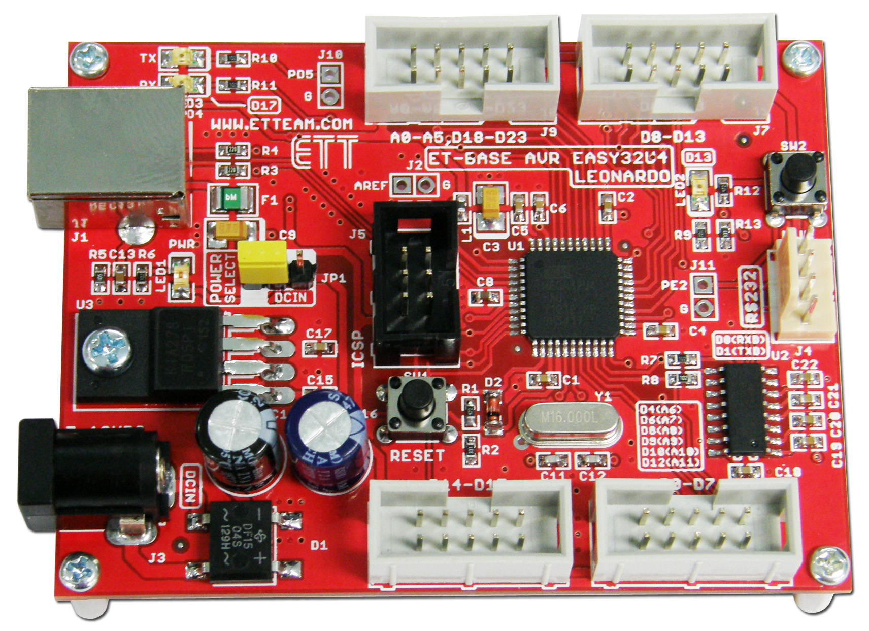
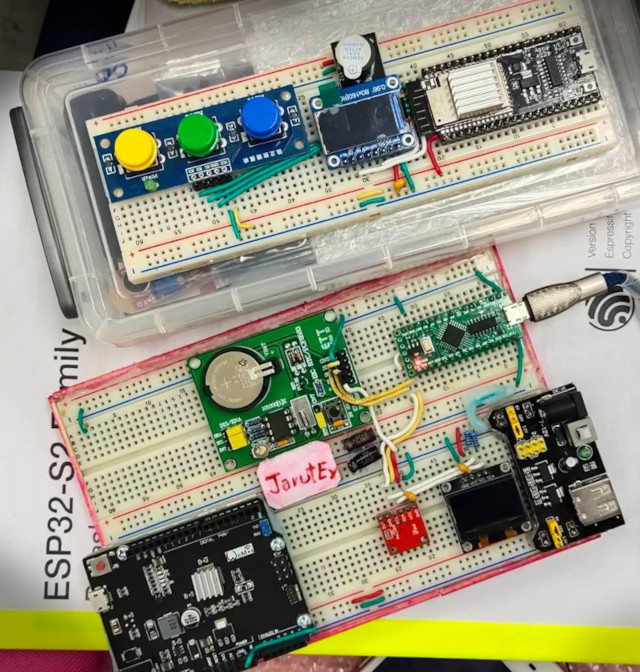
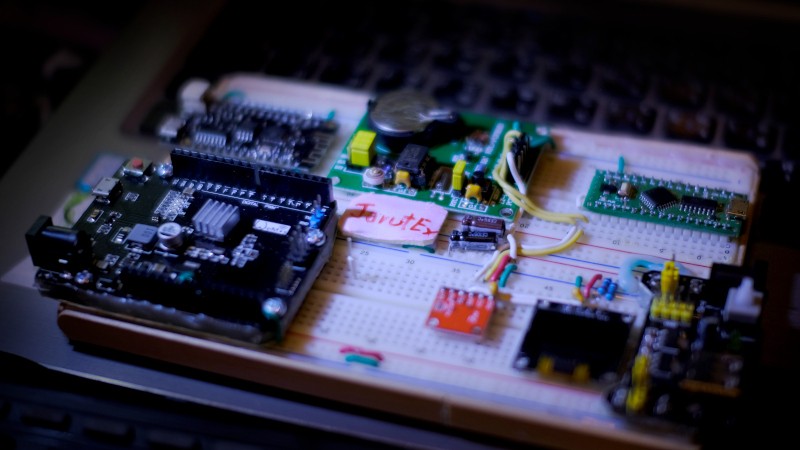
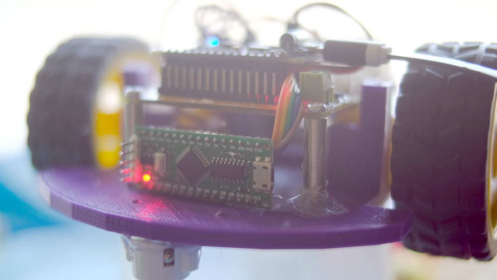
Based on the previous article that uses a single esp8266 for controlling the Agent, the number of pins that the esp8266 microcontroller (as written in the MicroPython article about machine.Pin) is limited. Many of the pins are used at boot up causing unintended errors such as the wheel spinning when the system starts and stops when the system finishes booting, etc. Therefore, in this article, a microcontroller board LGT8F328P is added as shown in Figure 1, or the reader may change to other Arduino family microcontrollers, such as Arduino Nano or Arduino Uno, etc. by giving that LGT8F328P is part of the Actuator that acts as a movement in the environment. It can be commanded to go forward, backward, turn left, turn right and stop, reducing the workload of the esp8266 and making it more responsive to WiFi communication.
Figure 1 LGT8F328P is integrated into a robotic car system to control the movement
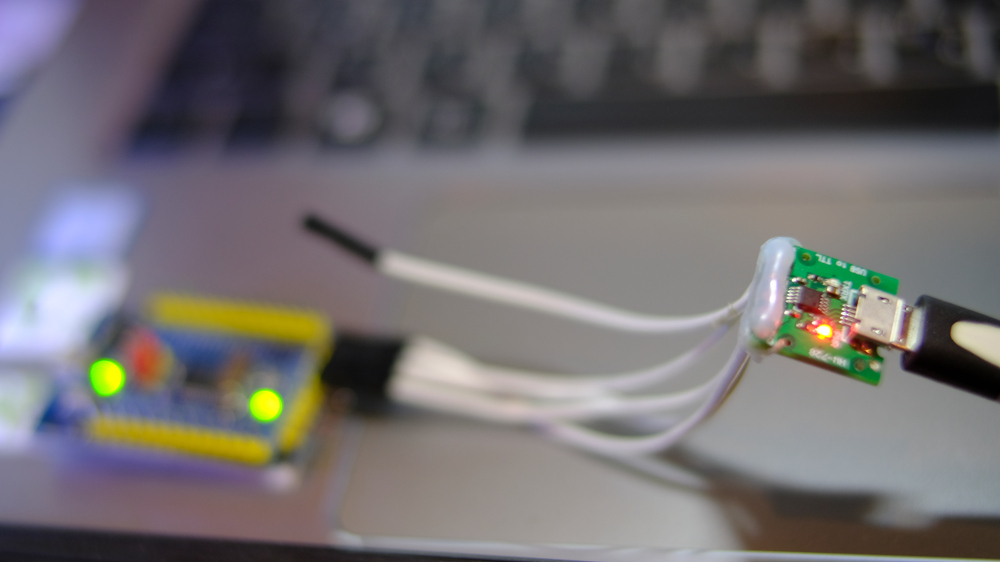
From the article recommending the use of the board STM32F030F4P6 that uses serial communication with the use of additional libraries that do not have enough memory. So we try to use SoftwareSerial of Arduino framework and use pins PA10 and PA9 to connect to RX and TX of USB-RS232 Converter Module as shown in Figure 1 and try to use it according to the settings of Arduino IDE as shown in Figure 2 and order toggle LED connected to pin PA4 found that when compiling the sample program is used, the ROM and RAM usage are 80% and 21% respectively as reported by the Arduino IDE as follows.
Sketch uses 13188 bytes (80%) of program storage space. Maximum is 16384 bytes.
Global variables use 876 bytes (21%) of dynamic memory, leaving 3220 bytes for local variables. Maximum is 4096 bytes.
From the article Controlling a Servo 2-Wheel Robot in the ESP8266+RoboServo and the DC electric motor in VisionRobo Car: Drive Motor, we have taken the 2nd built-in robot car from the Raspberry Pi to the ESP8266 to operate via WiFi using the guidelines from the ESP-01s+Relay article. Let’s rewrite Arduino’s C/C++ with the WebServer class from the ESP8266 article to MicroPython. Thus, by the end of this article, the robot can be operated in the first example by connecting a phone or communication device. Go to 192.168.4.1 and order it to go forward, backward, turn left, turn right, or stop.